
Sponsored by Hesse Mechatronics
By Mike McKeown and Dr. Dirk Siepe, Hesse Mechatronics
Wire bonding cylindrical battery packs
is becoming more mainstream in the alternative energy market these days. This
article will review the design guidelines for how to successfully implement a
wire or ribbon bonding process for battery packs using cylindrical lithium-ion
cells. It will involve everything between the battery pack housing to the
cylindrical cell itself.
At the
present time, there are a handful of methods of interconnecting cylindrical
cells to the busbar. Resistance welding, spot welding, laser welding and wire
bonding are the more common interconnection methods. Wire bonding utilizes
ultrasonic energy to have the wire or ribbon form an atomic bond with the
surface as the wire and surface share electrons. The aluminum oxide, which is self-limiting,
actually helps optimize the wire bonding process as the ultrasonic process
removes the oxide layer and exposes virgin aluminum to enable the transfer of
valence electrons.
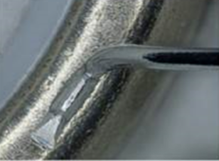
For wire bonding battery packs, Hesse prefers to bond onto the cell first and then up to the busbar. This is done for practical purposes as if for some reason you encounter a non-stick on the cell, you could easily rework it. We normally use a back-cut arrangement where the cutter blade is positioned behind the bond tool to enable the most clearance for the bond head.
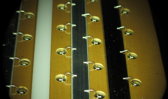
Photo courtesy of Purdue University Race Team.
Cell and Busbar Metallization
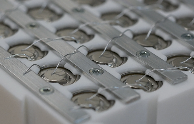
Almost all of the cylindrical cells have an electrolytic nickel over stainless steel metallization. For wire bonding with aluminum wire, it would be ideal if the metal can was aluminum as a mono-metallic system is optimum. As for the busbar material, it is best if it is also aluminum. We have found that Al1145 is the best metal. A thickness of 1-2mm should be sufficient, but it is not recommended to make the busbar too thick as this could inhibit bond head clearance in relation to the top of the cylindrical cell. We have also found success wire bonding to other Al such as 3003, 5052 6061 but one needs to review the technical specifications of these aluminum to ensure resistivity, conductivity, etc. If you need to use a Cu busbar, then you need to plate it with ENIG (Electroless Nickel Immersion Gold) or ENEPIG (Electroless Nickel Electroless Palladium Immersion Gold). These are off-the-shelf chemistries that are excellent for wire bonding. Refer to the IPC specifications for 4556 and 4552. The important aspect is to request a “mid-phos” bath of 4-11% as this is ideal for wire bonding. All busbar material should be half-hard temper. If you must wire bond directly to a Cu busbar, then you will need to clean the Cu prior to wire bonding. An emerging trend is to use heavy Cu wire. Refer to Figure 1 to view the Hesse Customer Solutions Battery Pack with heavy Cu wire.
Busbar Attachment to Matrix
There are numerous methods to attach the busbar to the “honeycomb” matrix. Some prefer to use an adhesive or epoxy method. The main issue to be careful of is to dispense the material beneath the busbar area where wire bonding will be done. We have not had much success with heat-staking the busbar as the heat-stake interconnection could become weak over time and cause the wire bond heels to fail prematurely due to excessive lateral movement. We have found that screws that extend through the battery pack have the best wire bond performance. In order to achieve this, the screws need to be evenly placed throughout the busbar. Do not just put screws on the ends of the busbar as you will encounter chamber issues. Refer to Figure 1 to see the position of these screws. The key item with the busbar is that it cannot move in X, Y or Z directions. The busbar has to be rigidly held to the matrix to ensure optimum wire bonding.
Bonding on the Negative
Wire bonding onto the negative terminal of a cylindrical cell is doable. Hesse utilizes unique pattern recognition algorithms to locate the negative section of the cell prior to wire bonding to ensure proper wire placement. If you do shear testing, remember to shear the bond in the direction away from the positive to avoid any short circuiting.
Process Guidelines
Cleanliness: Some companies do not have to clean their cylindrical cells prior to wire bonding but if needed, one could use a manual process of using a wire with IPA (Isopropal Alcohol). For more thorough cleaning, you could evaluate laser ablation or CO2 cleaning. A mechanical scrubbing process is also an option but be careful not to remove the nickel-plated layer and you have to vacuum the dust particles.
Bonding Wire: The main wire suppliers all recommend a less ductile wire as this you want the wire. You do not want to use too soft a bonding wire in relation to the harder electrolytic nickel surface of the cylindrical cell.
Fixturing: It is imperative that the battery pack is firmly held in place on the wire bonder’s working table. Just as it mentioned earlier in this article that the busbar needs to be rigidly held in place within the matrix, the entire battery pack cannot move during the wire bonding process. Any movement could inhibit wire bond quality.
Design Review: It is important to do a design review with the wire bonder company to ensure clearances are addressed with 3D models of the wire bond head.
Taguchi Techniques: We have found that by using a L9 Orthogonal Array could help get one an initial wire bond parameter window. There are more advanced Taguchi arrays that could then be utilized to further explore and statistically test out your wire bond parameters.
Wire Bond Quality: Hesse prefers to utilize the German Welding Specification, DVS 2811 Test Procedures for Wire Bonded Joints for setting up wire bond quality criteria in regards to pull and shear testing and visual aspects.
Wire bonding of battery packs for cylindrical cells can be easily implemented if these design guidelines are followed. Getting from design to production would be easier and resulting in higher quality yields will also be achievable.
Hesse Mechatronics is a manufacturer of wire, ribbon
bonders and smart welders. For more information, please contact sales@hesse-mechatronics.com
Source: Electric Vehicles Magazine
