

High-performance electric vehicles run with two, three or even more electric motors in the powertrain. Tuning the motor control is complex and requires precise performance analysis in order to test the desired driving characteristics. Early in the development process, the interaction of the individual inverters and electric motors is analyzed on powertrain test benches and in test vehicles. For this purpose, all power flows between the components have to be analyzed in real time with the raw data recorded.
Background
The driving characteristics are essentially determined by the architecture of the powertrain: Do two e-motors work on the rear axle or one e-axle each at the front and rear? In the future, there will be a wide range of variants, up to 4 motors for high-performance vehicles.
Performance analyses show whether the engine management system executes the control of the individual motors as expected during rapid changes of acceleration, braking, recuperation and reactions during load jumps or under full and partial load.
In further development phases, pre-defined test drive cycles are used to verify the performance data and the integration of the powertrain in the overall vehicle. The power measurement technology must be installed in the vehicle in order to be able to perform the measurements on road-to-rig test rigs and on the road. The measurement system must be able to operate independently in logger mode and also be integrated into the automation of test benches.
Challenge
The test bench measurement instrumentation shall perform both the measurement of all physical parameters and the simultaneous acquisition of ECU data with a harmonized measurement system. The measurement system must therefore include multi-channel, synchronized, electrical and mechanical performance analysis, as well as simultaneous high-voltage safe temperature measurement to analyze whether components are operating within the specified temperature range. All values must be calculated in real time in order to be able to directly detect fault reactions online at the control room or in the vehicle.
Special requirements are placed on power analysis: In all AC lines to the electric motors, the effective power of the individual motor windings must be determined in order to validate the wheel-specific control of the inverters. For accurate power analysis, the measurement data must be acquired synchronously. Especially current and voltage measurements must be phase-synchronized to accurately calculate electrical power in real time.

The Vector CSM E-Mobility Measurement System Solution
With the E-Mobility Measurement System, complex powertrains can be easily instrumented, and are scalable, for power measurement.
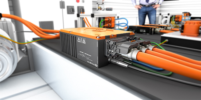
Active High-voltage Breakout Modules (HV BM) are used for power measurement. The HV Breakout Modules synchronously measure the high currents and voltages directly from the inner conductor of the power cable via temperature-compensated shunt modules. At the same time, A/D conversion and protocol conversion to EtherCAT or XCP-over-Ethernet are performed on the shunt modules inside the breakout modules. The HV BM 1.2 is used for single phase DC before the inverter and HV BM 3.3 breakout modules are used to measure 3-phase AC after the inverter.
Figure 1 shows a power analysis on a drive train that has one E-axis at the front and one at the rear. High-voltage Breakout Modules (HV BM) are inserted directly into the high-voltage cables for power measurement. Two HV BM 3.3 measure the AC currents and voltages between the E-motors and the power electronics. Two HV BM 1.2 measure between the HV battery and the inverters. They are each networked via EtherCAT® with an HV BM 3.3 and synchronized in time. The HV BMs measure currents and voltages up to ±2,000 V / ±2,000 A.
The power measurement circuit is already installed in the HV Breakout Modules 3.3. The AC phase currents (I1, I2, I3) are measured directly, and the AC phase-to-phase voltages between the phases (U12, U23, U31) are measured synchronously. Sampling is performed at 2 MS/s in each case.
Two CNT4 evo counter modules are used to acquire speed and torque at the axle shafts for mechanical performance analysis. High-voltage safe temperature measurement is performed with HV TH MiniModules (HV THMM). The modules are connected as a measurement chain via CAN and also networked with the HV BM 3.3. These work as gateway for all connected EtherCAT® and CAN measurement modules. A wide range of measurement modules for HV-safe measurements can be easily integrated for the acquisition of additional values.
Both HV BM 3.3 send the measurement data directly via XCP-on-Ethernet to the measurement computer or the Vector Smart Logger. Vector Smart Loggers are powerful and robust hardware platforms specially designed for time-synchronous parallel recording at high sampling rates of fast measurement modules, bus messages, video streams, radar raw data and ECU-internal measurement data in the vehicle.
A PTP grandmaster clock is included in this Smart Logger and the measurement modules are synchronized more precisely than 1 µs via PTP (PTP: Precision Time Protocol according to IEEE1588 standard).
The ECU data for power electronics and electric motors can be recorded via a Vector interface VX1000. The ECU data and the physical measurement data from the CSM measurement modules are synchronized with the Vector Smart Logger via PTP.
Vector eMobilityAnalyzer
The eMobilityAnalyzer is a standard library of pre-defined functions available in the popular software packages CANape and vMeasure exp from Vector Infomatik. It simplifies analyses in the development of electrified vehicles.
The eMobilityAnalyzer directly determines the efficiencies in real time from the measured raw data. This allows the load spectrum of the inverter and e-motor to be examined in detail, for example the efficiency in the various driving situations in the transition between acceleration, braking and recuperation, when the efficiency drops at low currents.
The energy flows are also analyzed to determine the energy consumption of the two e-axles during driving cycles. This allows fine-tuning of the motor control for different driving modes, driving dynamics and load conditions.
Benefits
The decentralized design of the E-Mobility Measurement System makes it easy to instrument test benches and test vehicles with the same measurement technology. Instrumentation and measurements in component and powertrain test benches are identical to those in test vehicles on vehicle and chassis dynamometers; thus a consistent measurement toolset throughout the development process
Multi-channel power analysis can be installed easily and quickly in powertrains with multiple electric motors, for example in all-wheel drive or utility vehicles. If, for example, a four-motor all-wheel drive system is to be analyzed, the measurement configuration can be doubled as shown in Fig. 1. The power analysis can then be performed on 4 engines and 4 inverters simultaneously. This means that even the most complex powertrains can be analyzed.
Read the full application example on www.csm.de/ev-usecase .
Source: Electric Vehicles Magazine
